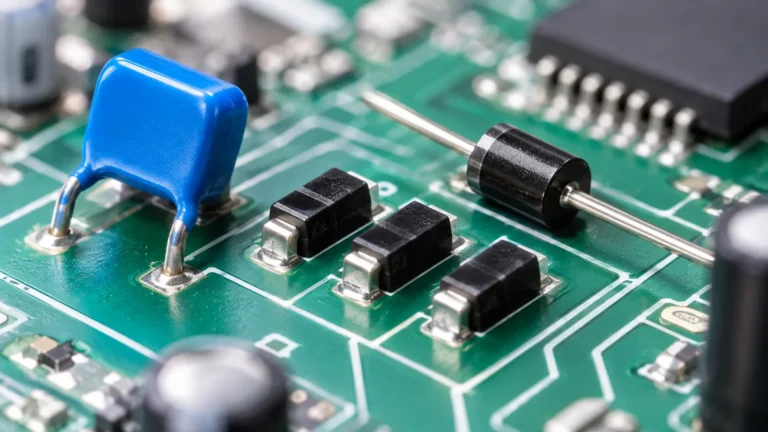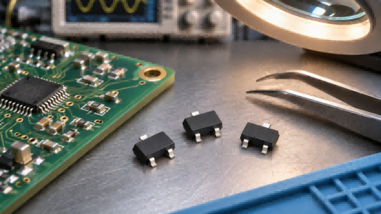
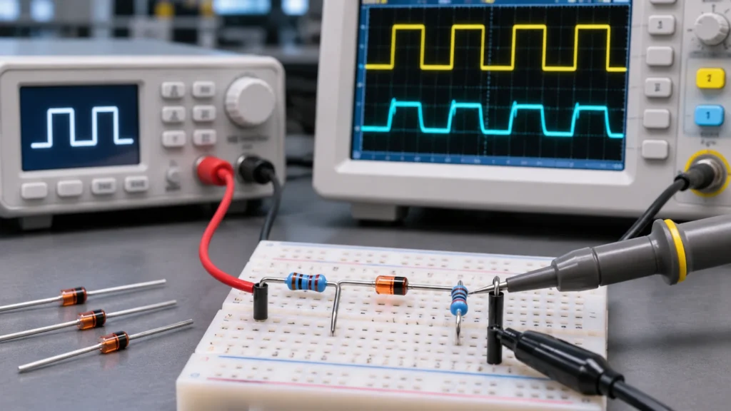
A switching diode is a semiconductor device designed for rapid transitions between conducting and blocking states. It is commonly used in digital logic, signal clipping, and pulse circuits where fast switching is essential.
But if most diodes already allow current to flow in one direction, what makes a switching diode different? The answer lies in its switching characteristics, particularly reverse recovery time and junction capacitance, which can affect signal performance in high-speed circuits.
Understanding these differences helps explain when a switching diode is more suitable than a conventional rectifier diode and which specifications matter most in real applications. This article explores how switching diodes work, where they are used, and how to select the right device for a circuit.
What Is a Switching Diode?
A switching diode is a type of semiconductor diode optimized for rapid switching between forward conduction and reverse blocking. Most conventional switching diodes use a silicon PN junction and are designed for relatively low-current signal applications where quick electrical transitions are important.
Switching diodes are commonly classified as small-signal diodes because they are frequently used in circuits that process low-power electrical signals rather than large amounts of electrical power. The terms small-signal diode and fast switching diode often overlap, although they emphasize different characteristics. Small-signal describes a general application category, while fast switching highlights the device’s ability to change conduction states quickly.
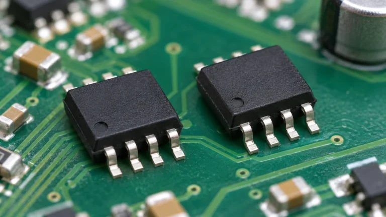
These devices are available in several physical configurations, including axial-leaded packages for through-hole assembly and compact surface-mount packages for modern PCB designs. Common examples include 1N4148 and related surface-mount variants. Different package versions may have different electrical and thermal ratings, even when they belong to the same general diode family.
The defining advantage of switching diodes is not simply their ability to conduct in one direction, but their suitability for circuits requiring controlled, rapid changes in current flow.
How Does a Switching Diode Work?
A switching diode operates by controlling current through a semiconductor PN junction. Its behavior depends primarily on the voltage applied between its anode and cathode. By changing the polarity of this voltage, a circuit can move the diode between conducting and blocking conditions.
Under forward bias, the anode is at a higher electrical potential than the cathode, allowing current to flow when sufficient forward voltage is applied. In an idealized circuit, this resembles a closed switch. However, a real silicon diode develops a forward voltage drop that varies with current and temperature. As a result, the voltage and current delivered to the connected circuit depend on the diode’s characteristics and the surrounding components.
Under reverse bias, the cathode is at a higher potential than the anode. The diode blocks most current, behaving approximately like an open switch as long as its reverse-voltage rating is not exceeded. A small reverse leakage current may still flow, and the junction retains electrical capacitance even while the diode is not conducting significant forward current.
Switching between these conditions is not perfectly instantaneous. When a previously conducting diode becomes reverse-biased, its internal electrical state must change before normal reverse blocking is fully established. This transitional behavior becomes increasingly important in circuits with rapid voltage changes.
In practical signal circuits, the diode’s switching state also depends on the applied bias and signal amplitude. For example, insufficient forward bias may prevent part of an AC signal from passing as intended, while an unexpected change in signal amplitude may cause clipping. This is why a switching diode should be understood as a real semiconductor component rather than a perfect electronic switch.
How Is a Switching Diode Different from a Rectifier Diode?
The main difference between a switching diode and a rectifier diode is their intended operating requirements. Switching diodes typically prioritize fast transitions and low-power signal handling, while conventional rectifier diodes are commonly optimized for converting alternating current into direct current and handling larger currents.
Both devices can conduct current under forward bias and block current under reverse bias. Their underlying behavior is similar, but differences in device construction, current capacity, reverse recovery characteristics, and power handling make them suitable for different applications.
| Feature | Switching Diode | Rectifier Diode |
|---|---|---|
| Primary Function | Fast signal switching | AC-to-DC rectification |
| Typical Current Handling | Relatively low | Often higher |
| Switching Speed | Generally optimized for rapid transitions | Depends on rectifier design |
| Reverse Recovery | Usually short in fast-switching types | Varies from standard to fast-recovery types |
| Junction Capacitance | Often relatively low | Varies with device structure and rating |
| Typical Applications | Digital logic, signal clamping, pulse circuits | Power supplies, AC/DC converters, power circuits |
| Main Selection Factors | Switching speed, capacitance, voltage and signal current | Current, reverse voltage, losses and recovery performance |
For example, a small-signal logic circuit may require a diode that can respond quickly to changing voltage levels without introducing excessive capacitive loading. A power supply rectifier, by contrast, may need to carry substantially higher forward current while tolerating reverse voltage and dissipating heat safely.
However, it would be incorrect to assume that every rectifier diode is slow. Fast-recovery and ultrafast rectifier diodes are specifically designed for applications involving frequent switching, including certain power-conversion circuits. Their recovery performance can be much faster than that of conventional rectifiers, even though their intended applications differ from those of small-signal switching diodes.
The practical distinction is therefore based on application requirements rather than a rigid separation between two completely different operating principles. A switching diode may perform simple rectification within its ratings, while a rectifier diode may also be suitable for switching applications if its electrical and dynamic characteristics meet the circuit’s needs.
Switching Speed and Performance Characteristics
Fast switching is one of the most important characteristics of a switching diode, but speed is influenced by more than the time required for current to begin flowing. The behavior of the semiconductor junction during transitions, along with its capacitance, determines how the device interacts with rapidly changing electrical signals.
Two characteristics deserve particular attention: reverse recovery time and junction capacitance. They describe different aspects of diode performance and should not be treated as interchangeable measurements.
Reverse Recovery Time (trr)
When a PN junction diode conducts forward current, charge carriers accumulate within its semiconductor structure. If the applied voltage suddenly reverses, these stored carriers must be removed or recombine before the diode can fully recover its normal reverse-blocking behavior.
During this transition, a temporary reverse recovery current may flow. The interval associated with this recovery process is called reverse recovery time, usually represented as trr.
A shorter trr generally allows the diode to recover its blocking capability more quickly under specified conditions. This can be beneficial in pulse circuits and other applications involving frequent changes in current direction. Excessive reverse recovery can contribute to switching losses, unwanted current transients, and waveform distortion, depending on the circuit.
It is important to distinguish reverse recovery current from reverse leakage current. Recovery current is a transient phenomenon associated with a switching event, while leakage current is present under steady reverse-bias conditions.
Reverse recovery time also depends on measurement conditions. Forward current, applied reverse drive, and the test circuit can influence the measured value. Consequently, two diodes should not be compared solely by their published trr numbers without checking whether the measurements were obtained under comparable conditions.
Junction Capacitance and Signal Performance
Even when a switching diode is reverse-biased, its PN junction behaves partly like a small capacitor. This electrical property is called junction capacitance, commonly represented as Cj or Ct.
In high-frequency circuits, junction capacitance can affect signal transmission even when the diode is nominally OFF. It may create an unwanted path for alternating signals, increase capacitive loading, or contribute to signal attenuation and slower voltage transitions. These effects become especially relevant when a diode is connected to a high-impedance node or a signal path operating at high frequencies.
For example, two switching diodes might have similar reverse recovery times but different junction capacitances. In a circuit where the diode repeatedly changes from forward conduction to reverse blocking, recovery behavior may be important. In a circuit where the diode remains reverse-biased while high-frequency signals are present, capacitance may have a greater influence on performance.
Junction capacitance is also voltage-dependent, so Datasheet values must be interpreted using their specified reverse-bias and test-frequency conditions.
A short reverse recovery time does not automatically guarantee superior performance in every high-speed application. The importance of trr and junction capacitance depends on the signal characteristics, circuit impedance, operating voltage, and switching conditions.
Common Switching Diode Applications
Switching diodes are widely used in electronic circuits that require controlled signal flow, fast transitions, or voltage limiting. Their compact size and switching characteristics make them suitable for digital logic, signal conditioning, and low-power pulse applications.
Although these applications share similar operating principles, they do not always require the same electrical performance. Some depend primarily on switching speed, while others are more sensitive to forward voltage, reverse leakage, or junction capacitance.
| Application | Main Function | Important Characteristics |
|---|---|---|
| Digital Logic Circuits | Direct signals and implement simple diode logic functions | Switching speed, forward voltage |
| Signal Clipping and Clamping | Limit or shift signal voltage levels | Forward voltage, leakage, capacitance |
| Pulse and Waveform Shaping | Control pulse transitions and signal paths | Reverse recovery time, capacitance |
| High-Frequency Signal Circuits | Route or condition rapidly changing signals | Low junction capacitance, suitable switching characteristics |
In digital logic circuits, switching diodes can steer current between different signal paths or implement simple diode logic functions. Their ability to respond to changing voltage conditions makes them useful in low-power signal networks. However, forward voltage drops and available logic-level margins must be considered to ensure reliable operation.
A practical example is a signal-clipping circuit designed to prevent a sensitive input from rising too far above a reference voltage. When the input exceeds the reference by approximately the diode’s forward voltage at the resulting current, the diode begins conducting and diverts current through the clamp path. A series resistor or another suitable current-limiting element is typically needed to prevent excessive current. The actual clamping level depends on the diode’s forward voltage, current, and temperature rather than a fixed 0.7 V threshold.
Pulse-shaping and high-frequency circuits place additional demands on diode performance. Fast recovery can help reduce unwanted transient behavior when current direction changes, while low junction capacitance can minimize loading on sensitive signal paths.
Not every switching diode is suitable for every application. High-frequency signal circuits may require particularly low capacitance, while low-current sensing circuits may be more sensitive to reverse leakage. Dedicated protection devices may also be necessary when substantial electrostatic discharge or transient energy must be absorbed.
Key Electrical Specifications of Switching Diodes
When evaluating a switching diode, the Datasheet provides the electrical ratings and characteristics needed to determine whether the device can operate reliably in a particular circuit. These specifications describe both operating limits and performance under defined test conditions.
The following parameters are among the most useful when comparing switching diodes.
| Specification | Symbol | Practical Meaning |
|---|---|---|
| Reverse Voltage | VR / VRRM | Maximum specified reverse-voltage capability |
| Forward Current | IF | Permitted current during forward conduction |
| Reverse Recovery Time | trr | Time associated with recovery after current reversal |
| Junction Capacitance | Cj / Ct | Capacitive loading and coupling characteristics |
| Forward Voltage | VF | Voltage drop during forward conduction |
| Reverse Leakage Current | IR | Leakage current under reverse-bias conditions |
| Power Dissipation | PD / Ptot | Permitted power dissipation under specified thermal conditions |
One important distinction is the difference between absolute maximum ratings and normal operating conditions. Maximum ratings define limits that should not be exceeded, but they do not necessarily represent suitable continuous operating conditions. Forward current and power dissipation may also require derating as ambient temperature increases.
Electrical characteristics should always be interpreted alongside their test conditions. For example, forward voltage is usually specified at a particular forward current, while junction capacitance is measured at defined voltage and frequency conditions. Reverse recovery measurements likewise depend on the applied current and switching test circuit.
Comparing published specifications without checking these conditions can produce misleading conclusions. A diode with a lower stated trr or capacitance is not necessarily the better choice if the measurements were performed under substantially different conditions.
For engineering evaluation, the most reliable approach is to use the Datasheet as a complete set of operating limits and measured characteristics rather than selecting a device based on a single headline specification.
How Do You Choose the Right Switching Diode?
Selecting a switching diode starts with understanding the circuit rather than identifying the fastest available component. A suitable device must satisfy the required voltage and current conditions while providing the switching characteristics necessary for reliable signal operation.
The selection process can be divided into two stages: verifying basic electrical compatibility and matching dynamic performance to the application.
Check the Circuit’s Electrical Requirements
Before comparing switching speeds, establish the maximum electrical conditions the diode may experience.
Check the following:
- Reverse voltage: Confirm that the maximum reverse voltage, including relevant transients, remains within the device’s specified limits.
- Forward current: Verify continuous and peak current requirements, accounting for applicable pulse ratings.
- Power dissipation: Evaluate conduction losses and any significant switching-related losses.
- Operating temperature: Consider ambient temperature, thermal conditions, and relevant derating requirements.
- Package compatibility: Confirm that the package dimensions and terminal configuration match the PCB design.
A diode that offers excellent switching performance but cannot withstand the circuit’s voltage or current requirements is not a suitable choice.
Package selection also matters. Through-hole devices may be convenient for prototyping or certain assembly requirements, while SMD packages support compact PCB layouts. However, devices with similar package names are not automatically interchangeable.
Match Switching Performance to the Application
Once electrical compatibility has been established, evaluate the characteristics most relevant to the circuit’s actual behavior.
For rapid pulse switching, reverse recovery characteristics may be important. For high-frequency signal paths, junction capacitance can become a more significant consideration. Low-current or high-impedance circuits may require particular attention to reverse leakage, while low-voltage signal applications may be sensitive to forward voltage drop.
Consider an engineer redesigning a low-current signal circuit that originally uses a through-hole 1N4148 diode. The updated PCB requires a surface-mount component, so the engineer considers the 1N4148W. Rather than assuming the two devices are interchangeable because their part numbers are similar, the engineer first checks the maximum reverse voltage, forward current, and operating temperature requirements. Next, the engineer compares reverse recovery time and junction capacitance under their specified test conditions. Finally, the SOD-123 package dimensions, terminal orientation, and PCB footprint must be verified.
This example illustrates an important selection principle: a replacement diode must satisfy both the circuit’s electrical requirements and its physical assembly requirements. Similar part numbers or switching-speed specifications alone do not establish compatibility.
A different diode technology may sometimes be more appropriate. For example, Schottky diodes can offer low forward voltage and negligible minority-carrier reverse recovery, but their leakage current, reverse-voltage capability, and capacitance must still be evaluated for the intended application.
When replacing an existing switching diode, an electronic component cross-reference search can help identify potential alternatives. However, final compatibility must be confirmed against the application requirements and verified component specifications.
The most suitable switching diode is not necessarily the fastest device available. It is the one whose electrical limits and switching characteristics match the intended application.
Frequently Asked Questions
Is 1N4148 a switching diode?
Yes. The 1N4148 is a widely used silicon switching diode commonly found in signal switching, clipping, and low-current logic circuits.
Which diode acts as a switch?
A switching diode is designed for fast electronic switching, although other diode types can also perform switching functions under suitable conditions.
Are switching diodes the same as signal diodes?
The terms often overlap. Small-signal diodes describe a broad application category, while switching diodes emphasize fast switching performance.
Can a switching diode be used for rectification?
Yes. A switching diode can rectify signals when its current, voltage, thermal, and switching ratings meet the circuit’s requirements.
Why doesn’t a switching diode work like an ideal switch?
Real switching diodes have forward voltage drop, reverse leakage, junction capacitance, and finite switching behavior that can affect signal transmission.
Conclusion
Switching diodes are designed for rapid signal control, making them useful in digital logic, pulse shaping, and signal-conditioning circuits. Their performance depends on electrical ratings, reverse recovery characteristics, junction capacitance, and the operating conditions of the circuit.
Choosing the right device requires matching these characteristics to the application rather than focusing on switching speed alone. For engineering teams evaluating switching diodes and compatible alternatives, China Chip Depot provides semiconductor component and sourcing support.