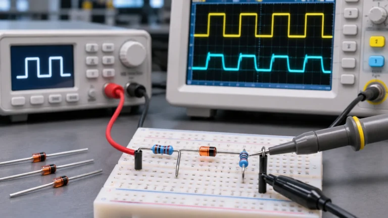
A TVS suppressor diode (Transient Voltage Suppressor diode) protects sensitive electronic circuits from sudden voltage spikes caused by electrostatic discharge (ESD), inductive switching, and electrical surges. It responds to transient overvoltage by conducting excess current and limiting the voltage across protected components.
However, not every TVS diode provides the same level of protection. A device with the wrong voltage rating, polarity, or surge capability may fail to protect the circuit, even when installed correctly.
Understanding how TVS diodes work is the first step toward choosing the right protection. This guide explains their working principle, unidirectional and bidirectional types, key electrical ratings, and practical selection considerations for common electronic applications.
What Is a TVS Suppressor Diode?
A TVS suppressor diode, also called a Transient Voltage Suppressor (TVS) diode, is a semiconductor protection device designed to limit short-duration voltage spikes that could damage sensitive electronic components. Unlike devices used for continuous voltage regulation, TVS diodes are optimized to handle brief overvoltage events and return to their normal operating state afterward, provided their electrical limits are not exceeded.
Voltage transients can originate both inside and outside an electronic system. Switching motors, relays, and other inductive loads can generate voltage spikes, while electrostatic discharge and externally induced surges can enter through power connections or communication interfaces. Although these events may last only a fraction of a second, their voltage and current levels can exceed the tolerances of integrated circuits, MOSFETs, and other electronic devices.
A TVS diode differs from an ordinary rectifier diode primarily in its intended function. Rectifier diodes are designed to conduct current in one direction, while TVS diodes are optimized for transient overvoltage protection. Although their avalanche behavior resembles that of Zener diodes, TVS devices are generally designed to withstand substantially higher short-duration pulse currents than ordinary voltage-regulation Zener diodes of comparable size.
TVS Diode Working Principle
A TVS diode protects electronic circuits by remaining largely nonconductive during normal operation and conducting substantial current when a transient voltage exceeds its protection threshold. It is typically connected in parallel with the circuit or signal line being protected, providing an alternative path for transient current.
Under normal conditions, the voltage across the TVS remains within its specified working range. The diode presents high resistance, allowing the protected circuit to operate normally with only a small leakage current through the protection device.
When a sufficiently large voltage spike occurs, the TVS enters avalanche breakdown in its reverse-biased operating direction. Its current increases sharply, diverting transient current through the protection path and limiting the voltage that appears across the protected circuit. This process is known as voltage clamping.
Once the transient subsides, the TVS returns to its high-resistance state, assuming the event has not exceeded its electrical or thermal limits. This behavior allows the device to provide protection against repeated transient events within its rated capabilities.
Importantly, a TVS diode does not maintain an absolutely constant voltage during a surge. The actual clamping level changes with the transient current and the diode’s electrical characteristics. Understanding this behavior is essential when evaluating whether a protection device can keep voltage within the limits of sensitive components.
Unidirectional vs Bidirectional TVS Diodes: What’s the Difference?
TVS diodes are commonly available in unidirectional and bidirectional configurations. Both protect electronic circuits from transient overvoltage, but they differ in how they conduct when the voltage polarity changes. Selecting the appropriate configuration depends on the normal voltage behavior of the protected line.
A unidirectional TVS behaves like a conventional diode when forward-biased and enters avalanche breakdown under sufficiently high reverse voltage. A bidirectional TVS provides avalanche-type protection for both positive and negative voltage excursions. These characteristics make unidirectional devices common in DC power protection and bidirectional devices useful for bipolar signals and certain AC applications.
| Feature | Unidirectional TVS | Bidirectional TVS |
|---|---|---|
| Voltage behavior | Different forward and reverse conduction characteristics | Similar protection characteristics for both polarities |
| Polarity | Installation orientation matters | Generally non-polarized |
| Typical applications | DC power rails, power inputs | Bipolar signal lines, selected AC circuits |
| Circuit symbol | Modified diode symbol | Opposing avalanche diode representation |
The transient voltage suppression diode symbol helps distinguish these configurations in circuit diagrams. A unidirectional TVS generally uses a modified diode symbol resembling a Zener or avalanche diode, while a bidirectional TVS is commonly represented by two opposing avalanche diode structures.
For a more detailed explanation of schematic representations and polarity markings, see our guide to TVS diode symbols.
The choice between these configurations should not be based on the application name alone. A unidirectional TVS can provide protection against both positive and negative transients through different conduction mechanisms, while bidirectional protection is often preferable when the normal signal itself swings above and below a reference potential.
TVS Diode Ratings and Electrical Characteristics
A TVS diode’s electrical ratings describe both its normal operating limits and its ability to withstand transient events. These specifications are usually provided in the device datasheet and allow designers to compare protection devices beyond their nominal voltage or package size.
Five parameters are particularly important when evaluating a TVS diode.
| Parameter | Meaning | Practical Significance |
|---|---|---|
| Reverse Standoff Voltage (VRWM) | Maximum specified reverse working voltage | Determines compatibility with normal circuit voltage |
| Breakdown Voltage (VBR) | Voltage measured at a specified breakdown test current | Indicates the device’s avalanche breakdown range |
| Clamping Voltage (VC) | Voltage across the TVS at a specified pulse current | Helps evaluate voltage exposure during a surge |
| Peak Pulse Current (IPP) | Rated maximum transient pulse current under specified conditions | Indicates surge current capability |
| Peak Pulse Power (PPP) | Rated peak power for a specified pulse waveform | Indicates short-duration pulse power capability |
These ratings describe different operating conditions and should not be treated as interchangeable. For example, a TVS with an appropriate working voltage may still allow a clamping voltage higher than a sensitive IC can tolerate. Likewise, a peak pulse power rating cannot be evaluated independently of the waveform and conditions used to specify it.
The relationship between VRWM, VBR, and VC is particularly important when comparing devices. VRWM defines the upper normal reverse working-voltage limit specified for the device. In a suitable application, the highest expected normal line voltage should remain within this limit, preventing unwanted avalanche conduction during normal operation.
VBR is the breakdown voltage measured at a specified test current. Because breakdown is not an instantaneous transition between two perfectly fixed voltage levels, datasheets commonly provide a minimum and maximum VBR range. This parameter helps characterize when the TVS begins conducting substantial reverse current, but it does not represent the voltage that will necessarily appear during a high-current surge.
VC represents the voltage across the TVS at a specified peak pulse current. During a surge, current flowing through the device causes its terminal voltage to rise above the breakdown region. The resulting clamping voltage is therefore generally higher than VBR at its relatively low test current.
For effective protection, the TVS must accommodate the maximum normal operating voltage while limiting the expected transient to a level compatible with the protected circuit. The relevant VC value must be checked at an appropriate surge current rather than assumed from the device’s nominal voltage alone.
Peak pulse current and peak pulse power provide another important constraint. For example, a 600W TVS rating specified with a 10/1000 µs pulse should not be directly compared with a different device’s 600W rating under an 8/20 µs waveform without reviewing the corresponding datasheets. Pulse duration, current shape, and thermal conditions influence what the device can safely withstand.
How Do You Choose the Right TVS Diode?
Selecting the right TVS diode requires balancing two essential conditions: the device must remain compatible with the circuit’s normal operating voltage while providing sufficient protection against expected transient events. A TVS with an unsuitable voltage rating may conduct during normal operation, while one with an excessively high clamping voltage may fail to protect sensitive components.
A practical selection process begins with the electrical requirements of the protected circuit rather than a particular TVS part number. The following five steps help narrow down suitable devices:
- Determine the maximum normal operating voltage. Identify the highest voltage the line can reach during normal operation, including supply tolerances and expected fluctuations. This is more useful than relying on the nominal voltage alone.
- Select an appropriate VRWM. Choose a TVS with a reverse standoff voltage compatible with the maximum normal voltage. For bidirectional signals, consider the full positive and negative operating range.
- Check the clamping voltage. Compare the TVS’s specified VC at the relevant surge current with the voltage the protected components can tolerate. Allow for additional voltage caused by circuit parasitics and the protection path.
- Evaluate surge current and pulse power. Ensure the device can withstand the anticipated transient conditions. Compare IPP and PPP using the appropriate pulse waveform, duration, and operating conditions.
- Confirm polarity, capacitance, and package. Verify that the TVS configuration suits the line’s voltage behavior, while its package and electrical characteristics satisfy the application requirements.
These steps help eliminate unsuitable devices before comparing specific products. Once the electrical requirements are established, you can review available TVS diodes by voltage ratings, surge capability, polarity, and package options.
Example: Selecting a TVS Diode for a 12V DC Circuit
Consider a circuit powered by a nominal 12V DC supply, with a sensitive controller connected to the power input. The goal is to protect the controller against transient voltage spikes entering through the supply line.
The first step is to establish the actual operating range. A nominal 12V supply does not necessarily remain at exactly 12V. If the input can reach 13.2V during normal operation, for example, the selected TVS must accommodate that voltage without unwanted avalanche conduction. The 13.2V value here is an illustrative design assumption, not a universal limit for 12V systems.
Next, consider the maximum transient voltage the controller and its associated circuitry can tolerate. A TVS with a 14V reverse standoff rating, for instance, does not necessarily clamp a surge at 14V. Its clamping voltage can be considerably higher, depending on the device characteristics and pulse current. The relevant datasheet values must therefore be compared with the protected circuit’s voltage limits.
Finally, evaluate the expected surge conditions and the device’s rated pulse capability. A TVS that meets the voltage requirements may still be unsuitable if the surge current exceeds its specified limits. Package size and thermal conditions should also be considered, particularly in equipment exposed to repeated electrical disturbances.
The key lesson is that a 12V power line does not automatically require a TVS diode with a 12V rating. The correct choice depends on the complete operating-voltage range, acceptable clamping level, and expected transient stress.
TVS Diode Applications and Circuit Placement
TVS diodes are used in electronic systems where sensitive components may be exposed to transient overvoltage. Although their basic protection mechanism remains the same, the electrical requirements vary between power supplies, communication interfaces, and industrial control circuits.
The following examples illustrate why the application matters when evaluating protection requirements.
| Application | Typical Protection Concern | Important Consideration |
|---|---|---|
| DC Power Inputs | Switching transients and externally induced surges | Operating voltage range, clamping voltage, surge capability |
| USB and High-Speed Data Lines | ESD and signal disturbance | Low capacitance, suitable protection voltage, signal integrity |
| Industrial Control Circuits | Inductive load switching and electrical transients | Surge capability, protection path, circuit layout |
For DC power inputs, TVS selection often focuses on voltage compatibility and the ability to withstand expected transient currents. High-speed communication interfaces introduce another challenge: the protection device itself can affect signal transmission. Excessive parasitic capacitance may increase signal loading, potentially degrading signal quality. This is why low-capacitance TVS diodes are commonly considered for high-speed data interfaces.
Correct circuit placement is equally important. A TVS diode is generally connected across the protected line and its appropriate return path. When protecting against transients entering through an external connector, placing the TVS close to that entry point helps intercept surge current before it travels through sensitive circuitry. The connection to the return path should also be kept short and low in impedance.
Even a correctly rated TVS may provide inadequate protection if long PCB traces or an unsuitable return path introduce excessive parasitic inductance. During a fast surge, these parasitic effects can create additional voltage across the protected circuitry. Effective protection therefore depends on both device selection and how the surge current is routed through the circuit.
TVS Diode Failure and Protection Limits
TVS diodes are designed to withstand transient electrical stress within their specified limits, but they cannot provide unlimited overvoltage protection. Excessive surge current, repeated overstress, sustained overvoltage, or unsuitable operating conditions can cause overheating and permanent damage. Depending on the device and failure mechanism, a damaged TVS may become short-circuited, open-circuited, or exhibit degraded electrical characteristics.
A particularly important limitation is that TVS diodes are not substitutes for continuous overvoltage protection. If a power supply remains above the allowable operating range, the TVS may conduct for too long and exceed its thermal capability. Similarly, a TVS can survive a transient while the protected circuit still experiences damaging voltage due to inadequate clamping or parasitic effects.
For reliable protection, both the expected electrical stress and the protected circuit’s tolerance must be considered. If a TVS fails repeatedly, simply installing another device with the same rating may not resolve the underlying problem.
Conclusion
A TVS suppressor diode provides fast protection against transient overvoltage, but effective protection depends on selecting the appropriate electrical ratings and applying the device correctly.
Understanding the relationship between working voltage, breakdown voltage, clamping voltage, and surge capability helps prevent common selection mistakes. For additional electronic component information and sourcing resources, explore China Chip Depot.
FAQs
What do TVS diodes protect against?
TVS diodes protect electronic circuits against short-duration voltage transients, including electrostatic discharge, inductive switching spikes, and specified surge events.
Is a TVS diode the same as a Zener diode?
No. Both can use avalanche breakdown, but TVS diodes are optimized for transient surge protection, while ordinary Zener diodes are commonly designed for voltage regulation or reference applications.
What is the difference between a TVS diode and a normal diode?
A normal diode is typically used for rectification or switching. A TVS diode is specifically designed to conduct large transient currents and limit overvoltage.
What causes a TVS diode to fail?
Common causes include surge energy beyond the device’s rating, sustained overvoltage, excessive heating, and incorrect device selection.
Can a TVS diode be replaced with another model?
Yes, provided the replacement meets the required voltage, clamping, surge, polarity, package, and applicable capacitance specifications. An electronic component cross-reference search can help identify potential alternatives, but electrical compatibility must still be verified.