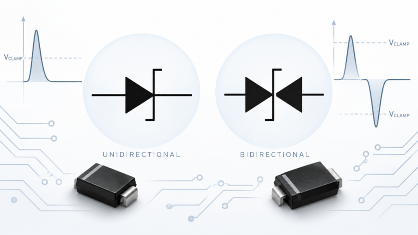
A TVS diode symbol represents a transient voltage suppressor used to protect circuits from voltage spikes. In schematics, a unidirectional TVS typically uses a diode-like symbol with defined anode and cathode terminals, while a bidirectional TVS uses a symmetrical breakdown symbol to indicate protection against both positive and negative transients.
However, TVS diode symbols can resemble Zener diode symbols, and their appearance may vary across schematics. Understanding these differences helps you identify the correct symbol, interpret polarity, and recognize TVS protection devices in actual circuit diagrams.
What Is the TVS Diode Symbol?
A transient voltage suppression diode symbol is the graphical representation of a TVS diode in an electronic circuit schematic. TVS stands for Transient Voltage Suppressor, a semiconductor device designed to limit short-duration overvoltage events such as electrostatic discharge (ESD), switching transients, and induced surges. During normal operation, the device presents high impedance within its specified working voltage range. When a sufficiently large transient occurs, it conducts current to help limit the voltage across the protected circuit.
The two most common representations are unidirectional and bidirectional TVS diode symbols. A unidirectional symbol resembles a diode with a modified cathode line, while a bidirectional symbol typically uses a symmetrical breakdown-diode representation. These circuit symbols describe electrical behavior rather than physical appearance. They do not identify the device’s package, voltage rating, surge capability, or exact part number.
What Is the Difference Between Unidirectional and Bidirectional TVS Diode Symbols?
The main difference between unidirectional and bidirectional TVS symbols is how they represent voltage polarity and conduction behavior. A unidirectional TVS conducts like a conventional diode under forward bias and enters avalanche breakdown under sufficient reverse bias. A bidirectional TVS, by contrast, exhibits breakdown behavior in both voltage polarities, typically with similar breakdown characteristics in each direction.
These differences matter when interpreting a schematic because the protected signal’s normal voltage range determines whether a particular TVS configuration is appropriate. A positive-only supply rail and a bipolar signal line may require different protection characteristics, even though both circuits need transient suppression.
Unidirectional TVS Diode Symbol and Polarity
A unidirectional TVS diode symbol is generally drawn as a diode-like symbol with a modified cathode line, similar to representations commonly used for Zener or avalanche diodes. Its terminals are identified as the anode (A) and cathode (K). The cathode-side marking is important because it indicates the direction in which the device is normally reverse-biased.
In a typical positive DC power protection circuit, the TVS cathode connects to the positive supply line, while its anode connects to ground or the circuit’s reference potential. Under normal operating conditions, the device remains reverse-biased with only a small leakage current. If a positive voltage surge exceeds its reverse breakdown region, the TVS conducts and limits the voltage according to its clamping characteristics.
A negative transient can also cause the same unidirectional TVS to conduct, but through its forward-biased junction rather than reverse avalanche breakdown. Therefore, unidirectional does not mean protection against only one transient polarity. It means the device has asymmetric forward and reverse electrical characteristics, which must be considered when interpreting its direction in a circuit.
For example, the 5.0SMDJ18A is a unidirectional TVS diode in an SMC package with an 18 V reverse standoff voltage (VRWM). Its specified polarity makes it a useful example of how a real device corresponds to a unidirectional schematic symbol. However, the symbol alone cannot reveal its 18 V rating or other electrical specifications.
Bidirectional TVS Diode Symbol and Polarity
A bidirectional TVS diode symbol represents a device capable of suppressing voltage transients in both polarities through breakdown behavior. It is commonly depicted using a symmetrical breakdown-diode symbol, although alternative representations appear in some schematic libraries and technical documents.
Unlike a unidirectional device, a conventional two-terminal bidirectional TVS does not have a fixed installation polarity. Reversing its two terminals generally does not change its intended protection function because its breakdown behavior is approximately symmetrical. This is particularly useful when the voltage of the protected signal normally swings above and below the circuit’s reference potential.
Consider a bipolar signal that varies between -5 V and +5 V. If a unidirectional TVS were connected directly between that signal and ground with its cathode on the signal line, its forward-biased junction could conduct during the normal negative portion of the waveform. A suitably rated bidirectional TVS avoids this problem by remaining in its high-impedance region throughout the normal positive and negative signal range.
The SMBJ24CA provides a practical example of a bidirectional TVS diode. It has a 24 V reverse standoff voltage and an SMB package. Its bidirectional classification identifies the general clamping behavior represented by its circuit symbol, although its particular voltage and power ratings must still be checked against the requirements of the protected circuit.
The following comparison summarizes the essential differences:
| Characteristic | Unidirectional TVS Diode | Bidirectional TVS Diode |
|---|---|---|
| Schematic Symbol | Diode-like symbol with defined polarity | Symmetrical breakdown-diode representation |
| Anode and Cathode | Defined terminals | No fixed external polarity for a conventional two-terminal device |
| Reverse-Bias Behavior | Avalanche breakdown above the specified threshold | Breakdown behavior in both voltage polarities |
| Forward-Bias Behavior | Conventional diode-like conduction | High impedance until breakdown in the opposite polarity |
| Typical Application | Positive DC power rails and unipolar signals | Bipolar signal lines and suitable AC circuits |
| Installation Direction | Depends on circuit polarity | Generally interchangeable terminal orientation |
The important distinction is not simply whether a circuit uses DC or AC power. Both types can protect circuits against positive and negative transients, but their conduction characteristics differ. The correct symbol and device configuration must be interpreted in relation to the normal signal voltage range.
Why Do TVS and Zener Diode Symbols Sometimes Look the Same?
TVS and Zener diode symbols can look identical because the devices share similar semiconductor breakdown behavior. In particular, a unidirectional TVS diode may be represented using the same Zener-style schematic symbol found in voltage regulation circuits. As a result, the symbol alone does not always distinguish a TVS diode from a Zener diode.
The main distinction lies in the intended application and electrical ratings. Zener diodes are commonly designed for voltage regulation, reference generation, and voltage limiting, including applications involving continuous power dissipation. TVS diodes are primarily designed to withstand short-duration transient currents and suppress potentially damaging voltage spikes. Although their operating principles overlap, their specified surge capabilities, voltage tolerances, and thermal characteristics can differ substantially.
For example, a diode-like symbol connected across a DC input line may represent a TVS intended for surge protection. A similar symbol in a voltage reference circuit may instead identify a Zener diode. The surrounding circuit provides useful context, but it is not conclusive because protection, regulation, and limiting functions can sometimes overlap.
Symbol variations introduce another source of confusion. Different schematic design tools, component libraries, and drawing conventions may use slightly different representations for avalanche and bidirectional breakdown diodes. IEC 60617 includes a designated symbol for a bidirectional breakdown diode, while practical schematics may also use modified diode shapes or back-to-back representations to communicate similar electrical behavior.
A back-to-back drawing also requires careful interpretation. It may illustrate the functional behavior of bidirectional breakdown or show two actual devices connected together. It does not automatically establish whether the physical circuit uses one packaged TVS or two separate components. The component references and associated part numbers determine how the schematic representation corresponds to the actual hardware.
For engineers reviewing unfamiliar diagrams, the distinction is important: similar symbols do not guarantee interchangeable components, and different symbols do not necessarily indicate different protection functions. The definitive device identity must come from the schematic’s component information and verified electrical specifications.
TVS Diode Symbols in Practical Circuit Schematics
Recognizing a TVS diode schematic symbol is only the first step. In an actual circuit diagram, its electrical connection provides important clues about the protection function. TVS diodes are commonly connected in parallel with the circuit node being protected, allowing them to conduct transient current when the voltage exceeds their specified operating limits.
The most useful way to interpret a TVS symbol is to examine the protected line, the device’s orientation, and the connection to ground or another reference node. Two common examples illustrate how unidirectional and bidirectional symbols relate to practical circuit behavior.
DC Power Input Protection Circuit
A typical DC power input circuit may include a unidirectional TVS diode connected between the positive supply rail and ground. The cathode connects to the positive input, while the anode connects to ground. The TVS is usually positioned near the power entry point to help suppress incoming voltage transients before they reach sensitive downstream components.
When examining this schematic, first identify the power input and follow the positive supply connection. If a diode-like protection symbol branches from the positive rail to ground, check its orientation. A unidirectional TVS connected with its cathode toward the positive rail is normally reverse-biased during regular operation.
For example, consider a 12 V DC input protected by a suitably rated unidirectional TVS. During normal operation, the input voltage remains below the device’s reverse standoff voltage (VRWM), and only a small leakage current flows through the TVS. During a sufficiently large positive transient, the diode enters avalanche breakdown and conducts current, limiting the voltage across the protected input.
The TVS does not necessarily clamp the input to exactly its breakdown voltage. The actual clamping voltage depends on transient current, device characteristics, and circuit conditions. Its rated clamping voltage (VC) is specified at a defined test current and must be evaluated against the voltage tolerance of the protected circuitry.
This example also explains why schematic orientation matters. Reversing a unidirectional TVS across a positive DC supply could forward-bias the device during normal operation, potentially causing excessive current rather than providing the intended protection.
Bidirectional Signal Protection Circuit
A bidirectional TVS diode may be connected between a signal line and a reference potential when the signal normally operates with both positive and negative voltage excursions. Its symmetrical schematic representation indicates that the device is intended to provide breakdown-based clamping for either transient polarity.
Consider an analog signal that varies between -5 V and +5 V relative to ground. A properly selected bidirectional TVS should remain in its high-impedance state throughout that normal voltage range. If a positive or negative transient exceeds the device’s breakdown region, the TVS conducts and limits the voltage excursion.
When reading this circuit, locate the signal path and identify the protection device connected across the signal and reference node. Unlike a unidirectional TVS, a conventional two-terminal bidirectional device does not require a specific terminal orientation. However, its working voltage range must accommodate the entire normal signal swing.
Some high-speed interfaces use specialized low-capacitance TVS diodes or multi-channel ESD protection arrays to limit unwanted loading of sensitive signal lines. These devices may use different schematic representations, particularly when several protected channels share a single package.
For either circuit type, the symbol should be interpreted together with the surrounding electrical connections. A recognizable TVS symbol provides an initial indication of the protection function, but it does not independently confirm that the selected device has suitable voltage, surge current, or signal-loading characteristics.
How Can You Confirm a TVS Diode from Its Schematic Symbol?
A TVS diode cannot always be identified conclusively from its schematic symbol alone. Some unidirectional TVS devices share symbols with Zener diodes, while different schematic libraries may represent similar protection functions using alternative graphics. The most reliable approach is to combine visual identification with the component information provided in the design.
Start by examining the symbol and its circuit connection. Identify whether the device is connected across a power input, signal line, or another circuit node. Then locate its reference designator, such as D1 or TVS1, and match it to the manufacturer part number in the bill of materials (BOM). Reference designators are useful for locating components, but their naming conventions do not establish the device type.
The datasheet provides the definitive electrical information needed to verify the component. Check whether the device is unidirectional or bidirectional, its reverse standoff voltage (VRWM), breakdown voltage (VBR), clamping voltage (VC), peak pulse current (IPP), and applicable surge test conditions. For bidirectional TVS diodes, confirm how the manufacturer specifies electrical characteristics for the two voltage polarities.
For example, the suffixes used in certain TVS product families distinguish unidirectional and bidirectional versions, but naming conventions are not universal. An exact part-number match is more reliable than guessing from a suffix or schematic symbol. Engineers comparing available TVS diodes should therefore verify the manufacturer’s specifications before selecting or substituting a component.
For production procurement and BOM-based component sourcing, China Chip Depot provides electronic component sourcing and replacement evaluation support. The relevant part number and verified electrical requirements should remain the basis for any sourcing or substitution decision.
FAQs
A TVS diode uses a diode-like schematic symbol. Unidirectional TVS symbols indicate defined polarity, while bidirectional TVS symbols generally use a symmetrical breakdown-diode representation. Exact drawing styles can vary.
Sometimes. Unidirectional TVS and Zener diodes may use identical or similar schematic symbols. Check the circuit context, part number, and datasheet to distinguish them.
A unidirectional TVS has an anode and cathode, so connection polarity matters. A conventional two-terminal bidirectional TVS generally has no fixed installation polarity.
SMD refers to surface-mount packaging, not a unique circuit symbol. An SMD diode may be a rectifier, Zener, Schottky, or TVS diode. Its schematic symbol represents its electrical function rather than its package.
Examine its diode-like symbol, polarity, and connection to the protected line. Then match its reference designator to the BOM and verify the exact part number against the datasheet